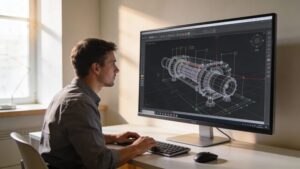
CAD & CAM Design is where imagination gets engineered—where sketches become precise models, and models become real parts you can hold, measure, and test. On Fabrication Streets, this category is your blueprint for turning concepts into manufacturable reality, whether you’re designing a simple bracket, a complex assembly, or a production-ready component headed for a CNC mill, router, or 3D printer. CAD (Computer-Aided Design) helps you build clean geometry, accurate dimensions, and smart constraints. CAM (Computer-Aided Manufacturing) takes that geometry and translates it into toolpaths, feeds, speeds, and machining strategies that shape material with confidence. Here you’ll dive into the full workflow: parametric modeling, assemblies, drawings, tolerances, and design-for-manufacturing choices that prevent headaches later. You’ll also explore CAM fundamentals like workholding, cutters, roughing vs. finishing passes, and how simulation helps you catch collisions before they happen. Whether you’re a hobby maker or building for industry, CAD & CAM skills unlock speed, precision, and repeatability—the secret sauce of modern fabrication. Let’s design smarter, machine cleaner, and build what you’ve been picturing.
A: CAD designs the part; CAM plans how a machine will make it.
A: Not always, but you still need toolpath-like planning via slicers and settings.
A: Commonly STEP for solids, DXF for 2D profiles, and STL for meshes.
A: End mills are round—add corner relief or redesign for tool radius.
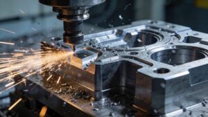
A: Vibration from tool deflection, poor workholding, bad speeds/feeds, or long stick-out.
A: Start with tool manufacturer guidance, then adjust for rigidity, material, and chip load.
A: A conservative facing or light adaptive roughing with a safe clearance height.
A: Simulate, verify setup, and do a dry run above the stock.
A: When you need access to more faces or tighter accuracy on critical datums.
A: Designing parts so they’re easier, cheaper, and more reliable to produce.